High Pressure electron magnetic resonance
Despite its fundamental importance pressure is a rather neglected variable in magnetic resonance experiments. Applying uniaxial stress to materials paramagnetic centres can provide unique information, it can break symmetry allowing centre symmetry ambiguities to be resolved, and for high symmetry centres it can allow the spin state to determined, for example the isotropic Gavacancy spectrum in GaP was shown to be S = 3/2. In addition, current semi-empirical models for calculating spin-Hamiltonian zero-field splitting terms require parameters obtained from pressure dependent EPR measurements on ‘model’ high symmetry transition-ion doped host crystals. The application of stress is of particular value in the study of defect centres in diamond and other semiconductors, and in piezoelectric materials.
This project is a collaboration with Prof. Mark Newton, University of Warwick, and aims to develop and implement diamond anvil pressure cells in loop-gap EMR resonator structures for high pressure EPR studies of materials. Development of high pressure cells has been pioneered at Warwick where they have been used to perform Raman measurements on diamond, applying uniaxial stresses up to approximately 4 GPa. However, further work is required before the technology can be translated to allow routine EPR measurements. An expected outcome of the project is that high pressure EPR resonators will be implemented and tested, one for operation with spectrometers at Dundee and St Andrews and one at Warwick, initially at 9.5 GHz but a further aim will be to investigate extending the technology to 34 GHz. An additional technological challenge to be approached will be to combine a high pressure cell with a cryostat for low temperature EPR measurements. A further possible aim will be to investigate the design and implantation of a hydrostatic pressure cell.
The high pressure system was constructed by myself (with the guidance of Ben Breeze and Matthew Dale) at the University of Warwick. I made my own modulation coils, resonator shields and coupling induction loop. It took approximately 4 weeks to build with this time including a basic EPR and pressure test. The system was brought back to Dundee for further work.
Implementing the device within the EMX spectrometer here in Dundee was not a trivial task. A mount to support the system between the magnets, connections to the bridge etc. had to be produced. The question on how we will apply pressure here in Dundee is still an open question at this point as we do not have a sophisticated pressurised gas regulated controller like Warwick. Initially we will most likely use small weights. As we have a large gain in pressure from the piston to the sample (approx. 340) due to the ratio of cross sectional areas, applied pressures do not have to be very large to observe a change in the sample.
The system has had its modulation coils calibrated and they can achieve a modulation amplitude of approx. 3 Gauss. Inital measurements on some standard samples and some SrTiO3:Fe crystals confirmed the system is operating adequately with respect to the EPR components. EPR on stressed samples, where an appriecable difference in the spectra is observed, is the next goal. I will update on this soon.
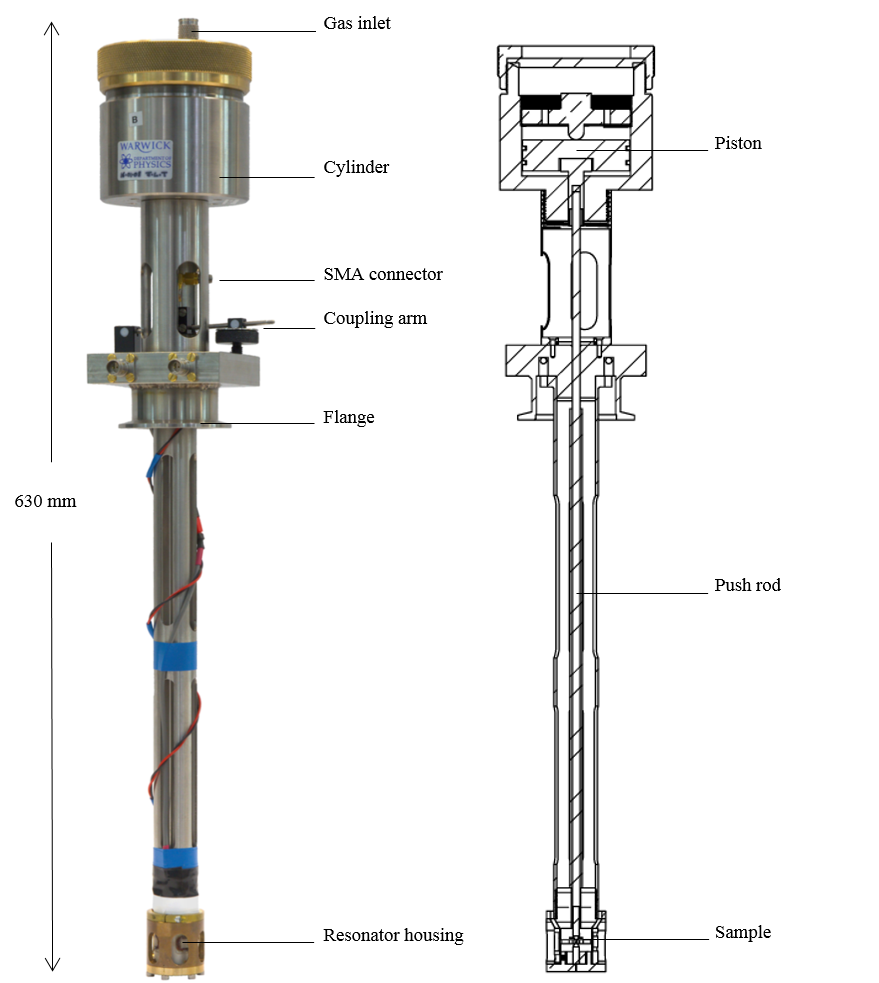
HIGH PRESSURE SYSTEM ENCLOSING A RESONATOR
I would like to acknowledge Mark Newton and his group at the University of Warwick. Ben Breeze and Matthew Dale in particular were extremely helpful in the construction of the high pressure probe. Below is an image of Matthew's system accompanied by a schematic diagram which shows the main features of the pneumatic pressure system. My system is identical barring some small cosmetic differences.
LOOP - GAP RESONATORS
The resonator housing encloses a Loop-Gap resonator. These are very different to a standard rectangular or cylindrical cavity resonator. They are typically small which is useful for for the high pressure system as it makes it easier to keep the metal pressure components outside the resonator.
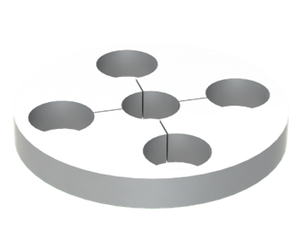
The image above shows the type of loop-gap resonators used in our system. The B1 magnetic field is confined to the loops (holes) and the B1 electric field is confined to the gaps between the loops. The number of loops/gaps and dimensions of the resonators can be altered for different microwave frequencies just as typical cavities can be.