Coupling a Loop-Gap Resonator (LGR), a lumped mode microwave resonant structure, to a transmission line
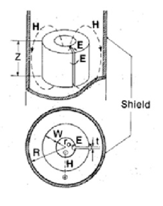
Loop-gap resonators can be coupled either inductively or capacitively. Below the principle of ‘mutual inductive coupling’ is presented using a 50 Ω coaxial cable as a microwave transmission line and LGR as a resonant structure in an EPR experiment. The basic structure of a LGR is presented below in Figure 1. The electric and magnetic components of microwave electromagnetic radiation are separated within the LRG, the magnetic flux (H) concentrating to the loop at the middle of the structure and the electric field (E) to the gap which acts as a capacitor.
Figure 2 presents a loop at the end of the coaxial cable. Because current flows through the loop the magnetic field is oriented perpendicular to it and the flux is concentrated to the centre of the loop. Figure 3 presents the principle of mutual inductive coupling, where the loop of the transmission line is brought to the vicinity of the LGR. The critical coupling is achieved by adjusting the distance (d) between the coupling loop and the LGR.
At critical coupling the magnetic flux at the loop of the transmission line (coaxial cable) extends around the LGR due to conducting nature of the LGR material (usually brass or Macor plated with Ag). At critical coupling the impedance of the transmission line matches the impedance of the LGR and no power is reflected from the resonator. When the resonance is achieved in an EPR experiment the sample (positioned in the central loop) absorbs energy, the critical coupling is lost and reflected power is detected as an EPR signal.
Further considerations:
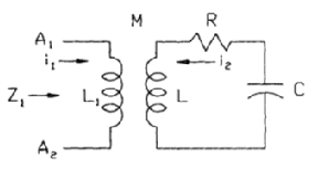
Equivalent electric circuit to mutual inductive coupling is shown in Figure 4.
The large inductance (L) of the LGR due to magnetic field generated in the loop is seen as a large inductive reactance by the external circuit (coaxial cable). Inductive reactance behaves as to oppose the alternating current in the external part of the circuit.
The inductive reactance can be cancelled by resonating with a capacitance, i.e. capacitor charging and discharging with 180 degree phase transition with the inductor (capacitive reactance is 90 degrees behind the current, inductive reactance 90 degrees in front of it). The impedance of the resonator will be very low or very high depending on whether the capacitor is in series or parallel to the resonator. When the critical coupling is achieved the impedance of the resonator is equal to the impedance of the transmission line (50 Ω typically). In Figure 4 Z1 is the impedance of the transmission line, A1 and A2 are the input terminals, C and R are the capacitance and resistance of the LGR, M is the mutual inductance between L1 and L, i1 is the current in the external part of the circuit (coaxial) and i2 is the current in the LGR part of the circuit. “Mutual inductance M is defined as ratio of magnetic flux linking the LGR loop to the current flowing in the coupling loop”.
The resistivity of the LGR material and the skin effect at high frequencies are the sources of the resistance R in the LGR circuit. Inductance is due to magnetic field and capacitance due to the gap in the LGR.
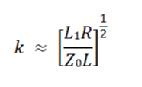
During mutual inductive coupling the distance (d) between the loop and the LGR determines the magnitude of mutual inductance (M in Figure 4). Graph 1 displays the coupling coefficient (k) as a function of distance (d) between the coupling loop and the LGR. Therefore the distance (d) should be set to maximize k and therefore the mutual coupling (M).
The coupling coefficient k can be represented by equation:
Impedance can be expressed by the following equation:
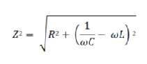
Where: Z = impedance (Ω), R = resistance (Ω), C = capacitance (Ω), ω = frequency (rad), 1/(ωC) = capacitive reactance, ωL = inductive reactance
The equation above applies for both the transmission line and the LGR. Because the coaxial cable has a set impedance (50 Ω), the matching of the transmission line and the LGR must be done at the LGR part of the circuit.
As stated above for a critical coupling the impedances between the coaxial cable and the LGR must match, so there is no MW power reflected back from the LGR. In addition to this it is important to match the capacitive reactance with the inductive reactance within the LGR. As they are both dependent on frequency (ω), the final critical coupling is achieved by finding a frequency where their magnitude is equal and their components cancel each other in the equation above. This is also when the maximum power is transferred from the transmission line i.e. there is only resistance (R) left in the LGR side of the circuit. This condition is called the Critical coupling: No MW radiation is reflected from the LGR and a maximum power is transferred between the transmission line and the LGR.
Any absorption of MW energy disturbs the coupling between the transmission line and the LGR, MW power is reflected back from the resonator and detected by the detector.
References used for this web note:
-
Mehdizadeh M.; Ishii T. K.; Hyde J. S. and Froncisz W., Transactions on Microwave Theory and Techniques, Vol. MTT-31, No. 12, 1983, pp 1059
-
Rinard G. A.; Quine W. R.; Eaton S. S. and Eaton G. R., J. Magn. Reson. A., Vol. 105, 1993, pp 137
 |
|
Figure 1: General structure of LGR (from reference 1) |
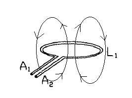 |
| Figure 2: Loop at the end of the coaxial cable (from reference 2) |
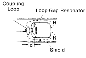 |
| Figure 3: Tuning of the LGR (from reference 1) |
 |
|
Figure 4: RLC circuit equivalent to coupling process
(from reference 2)
|
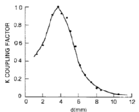 |
| Graph 1: coupling constant k versus distance d (from reference 1) |