
Micro - Stereo Lithography (MSL)
Background
MSL is a technique that is an example of a general approach known as rapid prototyping, whereby the techniques are used to build prototype models through a process in which the object is formed incrementally through the addition of successive layers. In the case of MSL, each layer is formed from liquid photopolymer resin that solidifies upon exposure to ultraviolet (UV) light. Typically a three-dimensional structure can be fabricated from carefully-designed two-dimensional slices, each of which is formed in turn. Our work in MSL covers two major areas: (i) microsystems, sensors and structural objects, and (ii) Work associated with RCNDE. For the former work, please see the separate webpage dedicated to this work, by clicking on the link below:
Micro-Stereolithography and Additive Manufacturing Lab
Fig. 1 shows a schematic of a typical MSL system. The mirror optics enable a lateral build resolution of 25 μm. The out-of-plane resolution for a system such as this can be as small as 7 μm, corresponding to the thickness of each deposited layer.
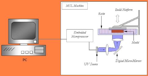
Figure 1: Schematic diagram of the MSL system
Fabrication of polymer-based CMUTs
A CMUT is an example of a structure which lends itself directly to fabrication by MSL techniques. In their simplest form they contain a rigid back surface, metallised to form a bottom electrode, with a pre-defined gap to an upper flexible membrane. This also has a thin metal layer on its top surface to form the capacitive element required for electrostatic operation.The cMUT devices were made in two sections, one section comprising a cavity and bottom electrode, and the other forming the membrane and top electrode of the device. Figure 2 shows a process flow diagram of the steps taken to produce polymer cMUTs. The electrode at the bottom of the cavity was produced by sputtering a 90nm planar layer of gold onto the patterned MSL model. Subsequent polishing of the model removed the gold from the raised surfaces. This technique of patterning electrodes has also been used by the authors to produce electromagnetic acoustic transducers (EMATs). The membrane section was metalised in the same way in order to produce the top electrode. The two halves of the device were then mated together, and pins added and connected using silver epoxy, to yield the finished device. Parameters such as cavity geometry, membrane thickness and other features can be added or changed by editing the CAD file used to fabricate the device.
|
|
|
|
|
1. MSL models created |
||
|
|
|
|
|
2. 90nm of gold sputtered and removed from unwanted areas by polishing |
||
|
|
|
|
|
3. Membrane section mated to cavity |
||
|
|
|
|
|
4. Electrodes added to complete transducer |
||


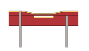
Figure 2: CMUT manufacture
MSL can be used to form many different shapes and surface features. Thus, it is possible to fabricate different backplate (bottom electrode) topographies. Fig. 4 shows two examples, the mesh-type backplate being particularly useful in cMUT operation, and a spiral grooved backplate. Figure 4 is a photograph of two such cMUT devices, fabricated by MSL techniques. These are 10 mm wide in active area, with a 60 micron thick membrane and an air gap of approximately 25 microns.
-
 (a)
(a) (b)
(b) (c)
(c)
Figure 3: Photographs of (a) a groove-type backplate and (b) a mesh-type backplate (top). Shown below in (c) is a photograph of two complete devices
Polymer CMUT characteristics
(a) Transient operation in air
Field plots were also performed, illustrating the directivity of the devices in air. The results are shown in Figure 4 for (a) transient excitation and (b) when driven with a 500 kHz tone burst. As expected, the use of a tone burst introduced a greater degree of side lobe activity, with an increase in directivity.
|
|
|
|
(a) |
(b) |
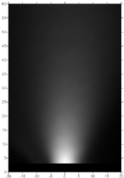
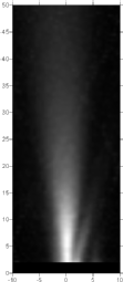
Figure 4: Beam patterns of MSL cMUTs driven by (a) a transient voltage and (b) a 500 kHz tone-burst. Dimensions are in mm.
(b) Operation in water immersion
Experiments were also conducted in water immersion. Here, the cMUTs were encased in a waterproof enclosure. This enclosure was sealed using silicone rubber, with only the front electrode in contact with the water. The transducers were driven with ton-burst signals, and the resultant waveform detected using a wide bandwidth miniature hydrophone. Two examples are shown in Figure 5, where it is evident that the acoustic signal (S) has been detected in both cases after the noise (N) from the transmitting amplifier.
|
|
|
|
|
|
Figure 5: Waveforms (left) and spectra (right) for tone-burst excitation of the CMUTs in water immersion. Signals are shown at I MHz (top) and 2 MHz (bottom).
(c) Operation as ultrasonic detectors at a solid surface
The devices fabricated using MSL have been tested as possible acoustic emission sensors, with other applications being structural health monitoring. For these experiments, the cMUT was connected to a charge amplifier, and placed in contact with the surface using dry contact. Results for Lamb waves in a 2 mm thick aluminium plate are shown in Figure 6, where it can be shown that the MSL CMUT was able to detect both a0and s0modes in the plate.
|
|
|
|
(a) |
(b) |
|
Figure 6 - Results obtained using piezoelectric (longitudinal 10MHz) as a source and an MSL mesh transducer as a receiver for the generation and detection of Lamb waves on a 2mm thick aluminium plate. (a) The time waveform, (b) time-frequency domain plot to identify modes |
|
Conclusions
Micro-stereolithography (MSL) appears to be a low-cost method for producing CMUT-like structures using polymer substrates. The results indicate the the transducers can operate in air, water and at a metal surface. This work represents a preliminary look at the problem. We are now intending to develop the MSL technique further, so that the resolution of the technique can be improved, to give thinner membranes and hence greater sensitivity and bandwidth, perhaps to include piezoelectric and magnetic structures.