
Building a new Linear Dichroism Cell
Introduction to Linear Dichroism
Linear dichroism (LD) is a biophysical technique for probing the structure of aligned macromolecules by measuring the difference between the absorption of light that is polarised in planes that are perpendicular and parallel to the orientation direction of the macromolecules (For review see Bulheller, Rodger et al. 2007). Spectral data can be used to provide information on the relative orientation of different components of the structure, such as alpha helixes and the side chains of aromatic amino acids. It is also possible to monitor reaction kinetics by monitoring the change in LD over time.
A Conventional LD cell, with the solution under test (c) contained in a quartz capillary of inside diameter 3.0 mm (a), with a central 2.5 mm diameter quartz rod . The outer capillary rotates such that any filamentary proteins are aligned by shear forces in the gap between (a) and (b). The LD is calculated from the difference in absorption between light (d) that is polarised in a horizontal and vertical direction.
Figure 2 shows the arrangement of a LD cell which is able align filamentous proteins by using the shear stresses that result from Couette flow between an outer rotating capillary and a central rod (Marrington, Dafforn et al. 2005; Bulheller, Rodger et al. 2007). A disadvantage of the conventional cell for measuring kinetics is that the reaction components must be mixed prior to the final assembly of the cell and initiation of measurements, which results in the kinetics information relating to up to the first minute of the reaction being lost.
In order to overcome this limitation, and enable LD kinetics measurements to be made immediately after the reactants are mixed, a modified cell was developed where the central rod is replaced by a second small capillary through which the reactants can be fed, referred to as a nested capillary.
The New Cell
Figure 3 Modified LD cell. The outer capillary (a) is as before and contains the reaction mixture (c). The central rod is replaced by a second nested capillary (b) through which the reaction mixture is fed through a capillary feed tube (d) from a computer controlled syringe pump.
In the new cell being developed a quartz capillary was used in place of the central quartz rod shown in Figure 3. The first capillary evaluated had an outside diameter (OD) of 3 mm and an inside diameter (I.D) of 1 mm. Measurements were also made on capillaries that had been ground down to ODs of 2.95 mm (giving an inter capillary gap of 25 μm) and 2.7 mm (inter capillary gap of 150 μm) with emery cloth while the capillary was spun in a lathe, and then polished with diamond paste.
A technique was developed which allows solution A to be introduced into the outer capillary and a small quantity of a second solution B to be injected from a small reservoir held within the inner capillary. The two solutions are separated by an airlock. In order to minimise the quantity of solution B that was required, the feed capillary and syringe was filled with water, and separated by an airlock from solution B which was thus contained within a small volume within the inner capillary tube.
The sequence of events associated with loading the solutions and mixing them within the LD cell is shown in Figure 4. A 100 μL Hamilton® 1700 Luer tip glass micro-syringe mounted in an electric Syringe Pump from New Era Pump Systems inc was used to control fluid flow in and out of the inner capillary, under control of a computer program (8).
Figure 4 Sequence of events for loading nested capillary tubes. The inner capillary is filled with water (a), and then a small air bubble drawn in (b), followed by a quantity of solution B (red) (c). A second air bubble is drawn in (d,e), followed by 25 μL of solution A (yellow) (f). The inner capillary is then placed in the outer capillary (g), which has been preloaded with 35 μL solution A. Solution A is then expressed out of the inner capillary (h), helping ensure that the capillary is filled without air bubbles. Solution B is then forced to the end of the capillary, at which point the air lock sits at the end of the capillary and a measured amount of solution B can be injected into the cell (i). Finally the air bubble is sucked back into the capillary where it can continue to provide a seal between the two solutions. (j).
Between measurements, the outer capillary was washed three times with deionised water and once with ethanol and then air dried between all measurements. The inner capillary was only washed with water as an ethanol wash was found to make the inner surface too hydrophilic for the air bubbles to be stable.
Unless otherwise stated, all LD measurements were made from an average of three measurement runs from 180 to 350 nm. Measurements of the new cell were compared with those from a reference cell with a central 2.5 mm diameter quartz rod. Validation tests were performed with laboratory stock DNA solution diluted to a nucleotide concentration of 200 μM unless otherwise stated, which was used as solution A and water for solution B.
And did it work?
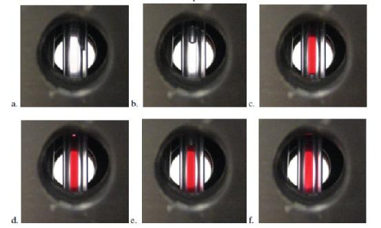
Figure 5 Visual monitoring of injection of solutions into Couette cell. Inner capillary placed into outer capillary, forcing water partway up the inter-capillary gap (a). Solution A then ejected into the outer capillary (b) until the red solution B was fully visible in the cell (c). With the outer capillary rotating, a small amount of solution B is ejected (d), which can then be seen moving up the inter capillary gap (e,f) over a period of approximately 10 seconds.
The injection technique was developed and validated using water as solution A and water coloured with red food dye as solution B. It is suggested that this technique be used to confirm quantities and technique prior to any experimental work with the nested capillaries. Operation can be monitored by placing the inner capillary into the outer capillary outside of the LD cell using a jig (Figure 6) that has been constructed for the purpose and also within the cell and monitor the operation visually.
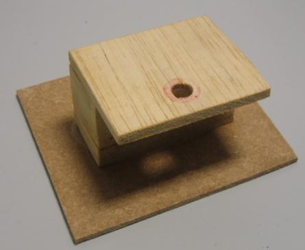
Figure 6 Jig constructed to allow contents of capillaries to be viewed while fluids are injected into the outer capillary using the inner capillary.
These visual tests identified one potential problem in that as the tube that connects the syringe to the inner capillary is bent as the inner capillary is moved between solutions and then to the CD cell itself, the internal volume changes slightly, and this can change the effect volume that is drawn out or expelled by up to 1 μL. This can be quite significant given the volumes being used, especially for the volume and stability of the airlock. Consequently, when validating the system before use, the dummy solutions (water and food dye) should be physically placed as close as possible to the positions where the real solutions will be placed. This process would require the user to develop a technique where this connector is moved as little as possible, and where the movement is as consistent as possible between measurements. It was found during testing that there needed to be slight adjustments of the quantities ingested and dispensed cater for different physical arrangements of the containers for solutions A and B.
The visual observations suggest that when the second fluid is mixed with the first, it takes of the order of 10 seconds for the fluid to diffuse throughout the visible inter-capillary gap.