
Anisotropic Sheet Metal
Introduction
When a bar, plate or sheet of metal is manufactured a number of working processes are involved that impart a crystallographic texture to the metal component. It is crucial that the final properties of the metal are suited to the process that would be applied in the next stage of product manufacture. As an example, one of the major users of sheet aluminium and steel is the canning industry, where the can bodies are drawn from the sheet metal. Incorrect texture results in increased wastage and production costs to the point where the metal may actually tear in the manufacturing process. Sheet metal manufacturers do not routinely use online inspection techniques to monitor the texture of the metal as it is produced, and most tend to perform X-ray pole figure [1,2] ‘spot checks’ on the final product.
For a number of years workers particularly in Japanand the UShave been working on the measurement of texture using a range of ultrasonic modes [3-8]. Much of this work has been done using narrow band EMATs as they generate unique ultrasonic modes without contacting the sample. We have pursued a slightly different approach by using broadband EMATs to perform the measurements in an attempt to increase the accuracy of the measurements.
The various modes that we have used are the zero order symmetric Lamb wave (S0) mode for thin sheets and plates and shear (SH) and longitudinal modes for thick samples. There is of course an overlap region where either technique can be used.
.
What sensors do we use and why do we use them?
EMATs are non-contact sensors and as such are particularly suited to measurements on moving components and eliminate any potential errors introduced by the use of couplants. The EMATs also have a small and negligible loading effect on the sheets and thus the stress free boundary conditions used to derive the Lamb wave dispersion relations are valid.
What do we measure?
Thin Sheets One linear coil EMAT generates the Lamb wave and a second detection EMAT detects the wave. Each EMAT (shown in yellow below) is fixed at either end of a fixed arm that rotates about its centre as shown below. A 1kg mass is applied to the centre of the sample in order to flatten the sheet to ensure that transit distances remain constant. As the sheets are often cut from a roll of metal it is crucial that the surface is not curved so that the true velocity can be calculated.
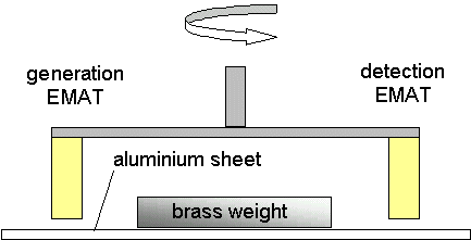
Figure 1
The above schematic diagram shows the experimental set-up used for generating and detecting the S0 mode Lamb wave in an aluminium sheet. The two EMATs were held a fixed distance apart on rotating arm and were separated from the sheet by a stand-off of 1mm.
The EMATs that we use to generate the S0 mode are broadband but have most of their frequency content centred around 130kHz and extending to around 300kHz. The out-of-plane displacement and Fast Fourier Transform for the S0 mode generated by the EMAT is shown in the figure below.
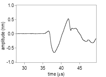
Figure 2
The above waveform is the out-of-plane displacement of the S0 mode as measured on the 250mm thick aluminium sheet, using a modified Michelson interferometer. Note that the absolute displacement has been measured in absolute terms (1.2nm peak-peak) by calibration of the interferometer.
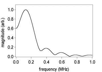
Figure 3
The above graph shows the calculated magnitude FFT of the out-of-plane displacement associated with the S0 Lamb wave mode.
The variation of the mode velocity (V) as a function of angle to the rolling direction can be approximated in the long wavelength limit [11] to:-
V2(a) = Q + AW400 – BW420 Cos(2a) + CW440 Cos(4a)
Where Q, A, B and C are constants dependant on the metal elastic constants and density and the Wklm coefficients are the Orientation Distribution Coefficients (ODCs) [9,10] that effectively give some measure of the texture.
By simple manipulation we can express these ODCs in terms of 3 distinct velocities measured at 0, 45 and 90 degrees to the rolling direction such that:-
4 CW440 = V02 + V902 - 2 V452
2 BW420 = V902 - V02
4 { Q + AW400 } = 2 { V452 + V02 } + { V902 - V02 }
Thus the ODCs can be extracted from just 3 velocity measurements. However this can be a risky policy as due to the nature of the functional dependence of the equations any small error in the velocity measurements can lead to errors in the calculated ODCs of several orders of magnitude higher than the error in velocity. However it is also possible to fit data over a range of angular measurements - this will increase the accuracy to which the ODCs are determined - this is the approach that we have chosen to take. In addition, scanning around a range of angles also shows any variation in the texture of the sheet, and this has been observed in several experimental samples.
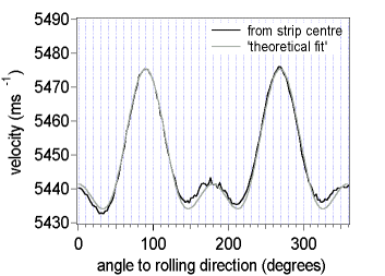
Figure 4
The above graph shows the measured velocity of the S0 mode on the 280mm thick aluminium sheet (obtained from the strip centre) as a function of angle to rolling direction, together with a ‘theoretical fit’. The angular dependent parameters for the ‘theoretical fit’ have been obtained from three discrete experimental values at 0O,45O and 90O to the rolling direction. Note that the ‘fit’ is necessarily a symmetric function around the rolling direction, whereas repeated measurements have shown that the experimental data is not symmetric at angles close to and either side of the rolling direction.
The most important point is that the measured velocities should be highly accurate relative to each other. Using the same EMATs on a fixed arm ensures that the relative accuracy is high. The calculation of the ODCs is fairly tolerant to relatively large variations in the absolute measured velocities provided that the relative error between the velocities is low.
Bulk Wave modes
With suitable correction factors the S0 Lamb wave can be used up to plate thicknesses of 0.15 times the wavelength of the Lamb wave so our current system can be reliably used up to plate thicknesses of a few mm. We are also able to generate SH wave modes with frequencies of up to 20 to 30MHz dependant on material properties. Thus we can generate SH waves in aluminium sheets down to 100microns thick. The first obvious application to use the SH mode for is thickness gauging and using Fourier analysis it is possible to achieve sub-micron accuracy [12]. Mode converted longitudinal waves are also generated in the sheet and can be observed for sheets thicknesses down to 200microns in aluminium.
Thus in the case of aluminium sheet we can accurately measure the relative velocities of the longitudinal waves and the SH waves with polarisations along and orthogonal to the rolling direction. These 3 velocities can be combined to obtain a measurement of the plate texture parameters W400 and W420. By measuring the shear wave propagating normal to the sample surface but with polarisation at 45O to the rolling direction the W440 ODC can also be obtained. Generating this SH wave is more difficult than generating the SH waves with polarisations along and at perpendicular to the rolling direction as the energy tends to be guided into the latter two directions.
References for further reading
[1] Roe RJ, Inversion of pole figures for materials having elastic anisotropy, J. Appl. Phys. 37, pp2069, 1966
[2] Thompson RB, Lee SS, Smith JF and Johnson GC, A comparison of ultrasonic and X-ray determinations of texture in thin Cu and Al plates, Met.Trans. 20A, pp243-249, 1989
[3] Liu YC and Alers GA, The anisotropy of Young’s modulus In cold rolled sheets of binary Cu-Zn alloys, Tans. Met. Soc. AIME 236, pp489-495, 1966
[4] Stickles CA and Mould PR, The use of Young’s modulus for predicting the plastic-strain ratio of low carbon steel sheets, Met. Trans. 1, pp1303-1307, 1970
[5] Davies GT and Goodwill DJ and Kallend RS, Elastic and plastic anisotropy in sheets of cubic metals, Met. Trans. 3, pp1677, 1972
[6] Papadakis EP et al, Development of an automatic ultrasonic texture instrument and its transition from laboratory to market: A model for technology transfer, Mat. Eval. 51, pp77-85, 1993
[7]Thompson RB, Lee SS and Smith JF, Relative anisotropies of plane-waves and guided modes in orthorhombic plates – implications for texture characterisation, Ultrasonics 25, pp133-137, 1987
[8] Alers GA and Sinclair AN, Measurement of the nine elastic constants of rolled plate from one surface, Rev. Prog. QNDE, 18, pp1695-1701
[9] Roe RJ, Description of crystalline orientation in polycrystalline materials, J. Appl. Phys., 36, pp2024-2027, 1965
[10] Sayers CM, J. Phys D:Appl. Phys.,15,pp2157-2165, 1982
[11] Li Y and Thompson RB, Effects of dispersion on the inference of metal texture from S0 plate mode measurements. Part1 Evaluation of dispersion correction methods, J. Acoust. Soc. Am., 91, pp1298-1309, 1992
[12] Dixon S, Edwards C and Palmer SB, High accuracy non-contact ultrasonic thickness gauging of aluminium sheets using Electromagnetic Acoustic Transducers (EMATs), accepted for publication in Ultrasonics, 2001