
Optical Pump Terahertz Probe Spectroscopy

Optical-pump terahertz-probe (OPTP) spectroscopy is used to follow the dynamic evolution of the far infra-red absorption of a sample following excitation by a femtosecond laser pulse. This technique allows us to study the dynamics of such properties as electron mobility and recombination dynamics on a picosecond to nanosecond timescale. The Figure shows our implementation of an OPTP spectrometer.
Pump beam: On this beamline the excitation pulse can be tuned to any wavelength in the range ~235-15000 nm using an optical parametric amplifier (TOPAS), seeded with a 1 kHz, 40 fs, 800 nm pulse (Ti:Sapphire Spitfire ACE) to create pulse powers of around 10 uJ / pulse. The power of the sample pump beam is controlled by a variable neutral density filter wheel. Appropriate filters are inserted to ensure spectral purity of the pump beam. The pump beam's path is fixed. Two mirror sets cover the range below and above 500nm.
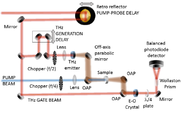
Figure 1. OPTP experimental setup.
THz probe: The THz probe pulse is generated by optical rectification using a fraction of the Ti:Sapphire's beam at 800nm, sent through a spintronic emitter. Off-axis parabolic mirrors are used to collect and focus the resulting THz radiation onto the sample being studied. The output THz beam is focused onto an electro-optic detection crystal along with a further 800nm pulse (the gate beam) in order to detect the time-domain waveform of the THz pulse transmitted through the sample. The resulting THz-induced change in the ellipticity of the gate beam response is detected using a Wollaston prism to separate s- and p-polarised light, and detected using silicon photodiodes (BPW-34) in a balanced detection arrangement. A high-precision oscilloscope (PicoScope) detects the THz pulse signal with and without the optical pump.
Detection crystals: Several options are available for detection: (1) electro-optic sampling with a 200um-thick <110> GaP on a 3.0mm <100> GaP substrate (bandwidth up to 6THz). (2) a 2.0mm-thick ZnTe (improved signal-to-noise, bandwidth up to 2.5THz), (3) a 0.5mm-thick <111> ZnTe for polarisation-resolved measurements of the orthogonal components of the THz electric field (Ex, Ey) (bandwidth up to 3.0THz) and ; (4) a 200um-thick <111> GaP on 500um <100> GaP also for polarisation-resolved studies (lower signal; bandwidth up to 6THz).
Delay stages: The stage that generates the delay between pump and probe pulses has a travel range of 500 mm with a resolution of 6 microns, reproducible to within 1.25 microns. This corresponds to a maximum temporal window of 3.3 nanoseconds at a resolution of 20 femtoseconds. The stage that scans the THz pulse has a travel of 150 mm with a resolution of 2 microns, giving a 1 nanosecond window and a 7fs resolution.
Sample environment: The THz pulse line is enclosed in a vacuum box which can achieve pressures below 10-4 mbar. A cryostat can be used to measure temperature dependent signals in samples allowing a range of accessible temperatures of 10-400 K.